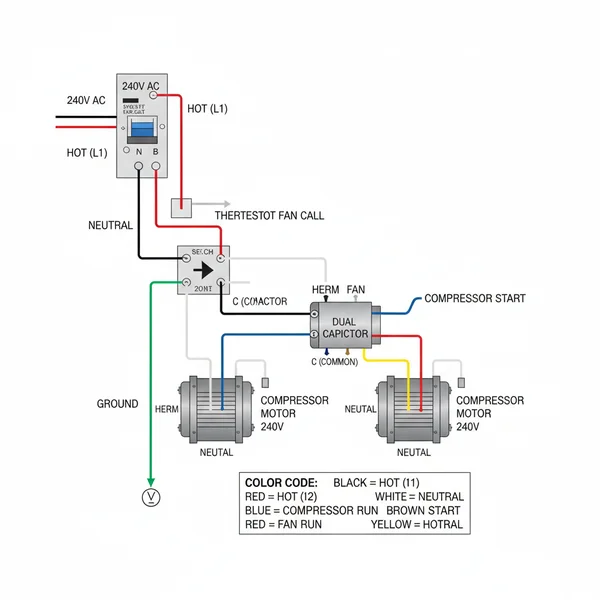
A 3 wire AC dual capacitor wiring diagram illustrates how to connect a dual-run capacitor to an HVAC unit’s fan and compressor motors. It details connections for the common terminal, herm, and fan terminals, showing proper routing for the hot wire and neutral wire. This ensures safe and efficient startup and continuous operation of both components.
📌 Key Takeaways
The diagram’s main purpose is to guide the correct electrical connection of a dual capacitor to HVAC fan and compressor motors.
The most important component to identify is the common terminal on the capacitor, which connects to the main power source.
A critical safety consideration is to always disconnect the hot wire power at the breaker before working with any wiring.
A practical application tip is to always match the microfarad (MFD) ratings of the replacement capacitor exactly to the original unit.
Use this diagram when installing a new dual capacitor, replacing a faulty one, or troubleshooting HVAC fan and compressor starting issues.
Understanding the intricate world of HVAC components can be daunting, but when it comes to vital parts like the dual run capacitor, a precise diagram is your most valuable tool. If you’re looking for a clear and comprehensive 3 wire ac dual capacitor wiring diagram, you’ve come to the right place. This guide will demystify the connections, ensuring your air conditioning unit runs efficiently and safely. A correct wiring diagram isn’t just helpful; it’s essential for proper function and preventing costly damage. By the end of this article, you will have a complete understanding of how to interpret the diagram, connect your capacitor, and troubleshoot common issues.
Decoding the 3 Wire AC Dual Capacitor Wiring Diagram
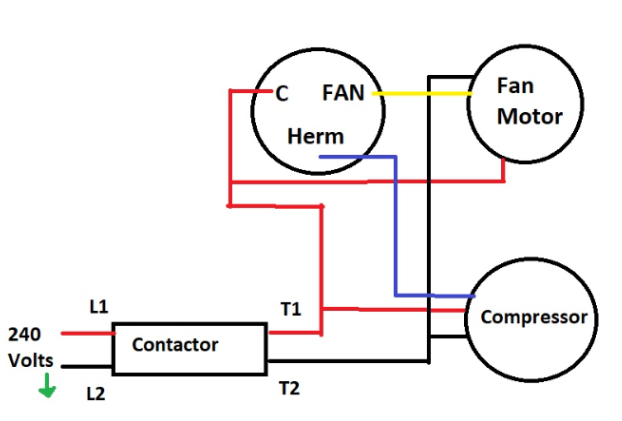
A dual run capacitor is a critical electrical component found in most central air conditioning units. It serves a dual purpose: providing the necessary electrical boost to start both the compressor motor and the outdoor fan motor. Unlike single capacitors, a dual capacitor combines these functions into one compact unit, indicated by its three terminals. These terminals are typically labeled “HERM” (for compressor), “FAN” (for outdoor fan), and “COMMON” (the shared power input). Understanding each connection point on your 3 wire ac dual capacitor wiring diagram is crucial for successful installation.
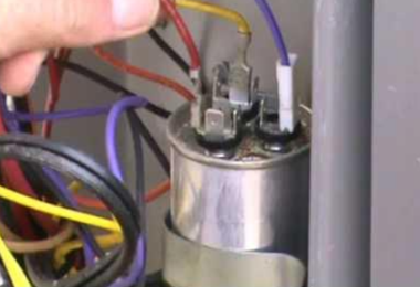
Visually, dual capacitors are cylindrical and often feature three distinct terminals on top, sometimes with different shapes or sizes. The common terminal is usually larger or clearly marked, serving as the central hub where the main power supply (often the hot wire from the contactor) connects. The “HERM” terminal sends power to the compressor, while the “FAN” terminal powers the outdoor fan motor. Each of these terminals is designed for specific wire connections, ensuring that the correct amount of current is delivered to each motor component at the right time. While color-coding on actual wires can vary by manufacturer, the principles of the diagram remain consistent: connecting the compressor, fan, and power source to their designated points on the capacitor.
💡 Key Information
A dual capacitor combines two capacitors into one unit, providing starting and running current for both the compressor and the fan motor in your AC system, streamlining wiring and improving efficiency.
3 Wire AC Dual Capacitor Wiring – Complete Guide
(Imagine a clear, color-coded wiring diagram here showing a cylindrical dual capacitor with three terminals labeled “COMMON”, “HERM”, and “FAN”. Wires would be shown connecting from the contactor (L1, L2, or Hot/Neutral) to COMMON, from the compressor to HERM, and from the fan motor to FAN. Arrows would indicate current flow. Wire colors might be standard: yellow/purple for HERM, brown for FAN, and usually thicker red/black for COMMON from the power source.)
Step-by-Step Guide to 3 Wire AC Dual Capacitor Wiring
Related: 3 wire ac dual capacitor wiring diagram
Working with electrical components requires precision and adherence to safety protocols. Before you begin any work, carefully review your 3 wire ac dual capacitor wiring diagram and gather the necessary tools. This guide will walk you through the process, ensuring you connect your dual capacitor correctly and safely.
⚠️ Warning
Always disconnect power to the outdoor unit at the circuit breaker and at the outdoor disconnect box before handling any electrical components. Capacitors can store a charge even after power is off; always discharge the capacitor before touching terminals. Use insulated tools.
Tools and Materials You’ll Need:
✓ Insulated Screwdriver (flathead for discharging capacitor)
✓ Nut Driver Set (for capacitor strap or mounting)
✓ Wire Strippers/Crimpers (if replacing wires or terminals)
✓ Multimeter (optional, but highly recommended for testing)
✓ Replacement Dual Capacitor (ensure matching MFD and voltage ratings)
Wiring Steps:
1. Power Disconnection and Safety First: As stated in the warning, cut all power to the outdoor unit. Open the outdoor disconnect box and remove the fuse block or pull the safety switch. Use your screwdriver with an insulated handle to carefully short across the terminals of the old capacitor to discharge any stored energy. This is a critical safety step to prevent electrical shock.
2. Photograph Existing Wiring: Before disconnecting anything, take clear photos of your existing capacitor’s wiring from multiple angles. This serves as your personalized 3 wire ac dual capacitor wiring diagram reference, invaluable if you get confused during the process.
3. Label and Disconnect Wires: Carefully observe the current connections. You will typically find a wire (often yellow or purple) connected to HERM (for the compressor), a wire (often brown) connected to FAN (for the fan motor), and one or more wires (often red or black, typically thicker gauge) connected to COMMON (from the power supply contactor). Label each wire as you disconnect it from the old capacitor. Pay attention to any brass screw connections or spades that might be shared on the common terminal.
4. Remove the Old Capacitor: Once all wires are safely disconnected, unstrap or unmount the old capacitor from its housing. Note its orientation and position for installing the new one.
5. Install the New Capacitor: Place the new capacitor in the same position as the old one and secure it with its strap or mounting bracket. Ensure it is stable and won’t vibrate loose. Confirm the MFD (microfarad) and voltage ratings match your unit’s requirements precisely.
6. Reconnect the Wires According to the Diagram: Now, using your photos and the universal 3 wire ac dual capacitor wiring diagram as a guide, reconnect the labeled wires to the corresponding terminals on the new capacitor:
• Connect the compressor wire (often yellow/purple) to the HERM terminal.
• Connect the fan motor wire (often brown) to the FAN terminal.
• Connect the main power wire(s) (often red/black, or the neutral wire/hot wire from the contactor) to the COMMON terminal. Ensure all wires that were on the old common terminal are transferred to the new one. Check the wire gauge to ensure it’s appropriate for the current draw.
Ensure all spade connectors are clean and seat firmly on the capacitor terminals. If you encounter a wire that seems to be a `traveler wire` in a general sense (e.g., carrying power between components), double-check its origin against your reference photos and the main power input points. The `ground wire` should always be connected to the unit’s chassis, not the capacitor.
7. Double-Check and Restore Power: Review all connections against your reference photos and the diagram. Confirm no loose wires or incorrect terminals. Close the outdoor disconnect box and restore power at the circuit breaker. Listen for proper startup of both the compressor and the fan motor.
Common Issues & Troubleshooting with Your Dual Capacitor Wiring
Related: 3 wire ac dual capacitor wiring diagram
Even with a clear 3 wire ac dual capacitor wiring diagram, issues can arise. Knowing common problems and how to diagnose them can save you time and money. The capacitor is a wear-and-tear item, and its failure often manifests in noticeable ways. If your AC unit struggles to start, or you hear a humming sound from the outdoor unit without the fan or compressor engaging, a faulty capacitor is a primary suspect.
•Motor Hums but Doesn’t Start: This is a classic sign of a failed capacitor. The motors receive some power but not enough to overcome inertia.
•Outdoor Fan or Compressor Not Running: If one component runs and the other doesn’t, it indicates a failure in that specific section of the dual capacitor (e.g., the “FAN” section failed, but “HERM” still works).
•Bulging or Leaking Capacitor: Visually inspect the capacitor for any swelling, particularly on the top. This is a clear indicator of internal failure and necessitates replacement. A burning smell around the unit is also a critical warning sign.
In troubleshooting, compare your actual wiring to the 3 wire ac dual capacitor wiring diagram to rule out incorrect connections. Use a multimeter to test the microfarad (MFD) rating of the capacitor. If the reading is significantly lower than the specified rating, the capacitor needs replacement. If symptoms persist after a correct replacement, or if you’re uncomfortable with electrical work, it’s best to seek assistance from a qualified HVAC professional to prevent further damage or personal injury.
Tips & Best Practices for Dual Capacitor Wiring
Implementing these tips and best practices will not only make your dual capacitor wiring easier but also extend the life and efficiency of your AC unit. Your 3 wire ac dual capacitor wiring diagram is a foundation, but these insights build upon it.
✅ Pro Tip
Always match the capacitor’s MFD rating exactly. While the voltage rating can be equal to or higher than the original, never install a capacitor with a lower voltage rating than specified by the manufacturer.
✓Quality Matters: Invest in a good quality, reputable brand of capacitor. Cheaper alternatives might fail prematurely, leading to repeated work. Look for capacitors with a robust outer casing and well-built brass screw terminals for secure connections.
✓Regular Inspection: During seasonal AC maintenance, visually inspect your capacitor. Look for any signs of bulging or leaking. Early detection can prevent unexpected breakdowns. Pay attention to the condition of the wires and their terminals.
✓Proper Wire Gauge: Ensure that the wire gauge connecting to your capacitor terminals is appropriate for the current it will carry. Using wires that are too thin can lead to overheating and potential fire hazards. The common terminal often carries higher current and may require thicker gauge wiring.
✓Secure Connections: Loose wire connections can generate heat and cause premature capacitor failure or intermittent operation. Ensure all spade connectors are tightly crimped and firmly seated on the capacitor terminals. Check any brass screw connections for tightness.
✓Protect from Elements: While usually inside a unit, ensure the capacitor and its connections are protected from moisture and extreme temperatures where possible, as these can degrade its performance over time.
By diligently following your 3 wire ac dual capacitor wiring diagram and integrating these best practices, you can ensure your AC unit operates reliably, saving on potential repair costs and extending the lifespan of your system. DIY repairs on AC units can be satisfying and cost-effective, but always prioritize safety and accuracy.
Frequently Asked Questions
What is 3 wire AC dual capacitor wiring diagram?
A 3 wire AC dual capacitor wiring diagram illustrates electrical connections for a dual-run capacitor in an HVAC system. It shows how the common terminal, herm (compressor), and fan terminals connect to their respective motors and power. This ensures the correct routing of the hot wire and neutral wire for safe and efficient operation of both key components.
How do you read 3 wire AC dual capacitor wiring diagram?
To read a 3 wire AC dual capacitor wiring diagram, locate the common terminal, fan, and herm terminals on the capacitor. Trace the hot wire and neutral wire from the power source to the capacitor and corresponding motors. Observe wire colors and symbols carefully. This method clarifies the electrical pathways for safe and accurate installation or troubleshooting.
What are the parts of 3 wire AC dual capacitor wiring?
Key parts of 3 wire AC dual capacitor wiring involve the dual-run capacitor itself, featuring a common terminal, a fan terminal, and a herm terminal (for the compressor). Other vital components are the compressor motor, fan motor, the hot wire supplying power, the neutral wire completing the circuit, and a ground wire for safety. The diagram connects all these.
Why is the common terminal important?
The common terminal on a dual-run capacitor is crucial. It acts as the shared electrical connection point for both the fan and compressor motor windings. Receiving the hot wire power, it distributes this internally to the fan and herm terminals. This enables both HVAC motors to start and run efficiently from a single capacitor, making it indispensable for system function.
What is the difference between Herm and Fan terminals?
The Herm terminal on a dual-run capacitor is for the compressor motor, providing its specific, higher microfarad (MFD) capacitance. The Fan terminal is for the outdoor fan motor, supplying a distinct, lower MFD rating. Both draw power from the common terminal, but are engineered for the unique capacitance requirements of their respective motors, ensuring optimal performance.
How do I use 3 wire AC dual capacitor wiring diagram?
To use a 3 wire AC dual capacitor wiring diagram, always de-energize the HVAC unit at the breaker, cutting the hot wire. Compare your capacitor’s existing connections with the diagram. Identify where the hot wire, neutral wire, and motor wires connect to the common terminal, herm, and fan terminals. Follow it for accurate and safe replacement or installation.
The Mass Air Flow (MAF) sensor is typically located in the engine’s intake tract, between the air filter box and the throttle body. It measures the amount of air entering the engine, sending this crucial data to the ECU for precise fuel mixture calculations. Identifying its location is vital for maintenance and troubleshooting. 📌 Key…
The 5.7 Chevy 350 belt diagram with AC illustrates the serpentine belt’s path around various engine components like the crankshaft, alternator, power steering pump, and AC compressor. It’s crucial for understanding the correct configuration of your vehicle’s accessory drive system and ensuring proper function of all connected accessories. 📌 Key Takeaways Main purpose of this…
An animal cell diagram illustrates the internal structure and various organelles, such as the cell membrane, nucleus, mitochondria, and cytoplasm, which perform specific functions vital for the cell’s survival and operation. It helps in visualizing how these components interact and contribute to cellular processes like energy production and genetic information storage. 📌 Key Takeaways Main…
The Chevy 4.3 V6 engine diagram visually details all major engine components, their arrangement, and connections. It is invaluable for understanding the engine’s layout, performing maintenance, locating parts for replacement, and troubleshooting issues. This resource helps mechanics and DIYers efficiently identify problem areas and plan repairs. 📌 Key Takeaways To visualize and understand the complex…
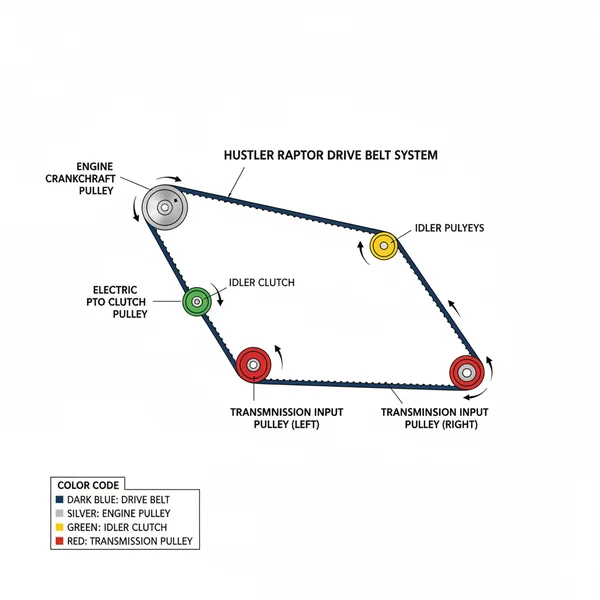
The Hustler Raptor drive belt diagram visually illustrates the component layout of the mower’s drive system, showing belt routing around pulleys and tensioners. It’s crucial for understanding the system’s configuration, aiding in correct belt replacement, tension adjustment, and overall maintenance to ensure optimal mower performance. 📌 Key Takeaways Main purpose of this diagram is to…
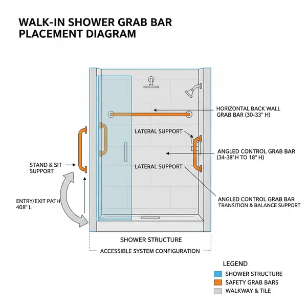
This diagram illustrates the ideal configuration for grab bar placement in a walk-in shower, ensuring maximum safety and accessibility. It details the precise height, angle, and orientation of each essential component to create a secure structure, preventing falls and supporting user independence within the shower system. 📌 Key Takeaways Main purpose of this diagram: To…